
#
Station Node - Pallet Station
#
Description
Corresponds to the palletizing station where the pallet will be placed, and the products to be palletized will be placed on it.

#
Node connection
#
Variables
#
Name
Name given by the user to the node.
#
Zone
Drop zone that will result in a specific signal mapping to the robot.
For more information, please consult the PLC integration manual and the wepall mapping manual.
#
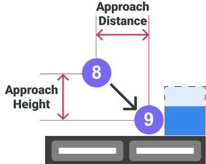
Approach Distance
Distance between points 8 and 9 from a top view (Vector formed between the X and Y coordinates of points 8 and 9). Indicated in millimeters.
#
Approach Height
This is the height from which the approach of the drop is made, e.g. to avoid bending the flaps of the box. This value must always be less than the height of the product. Indicated in millimeters.
#
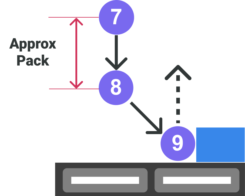
Approx Pack
Height from pack position to point 7
#
Pallet Station Z
Z coordinate (height) of the pallet, which determines the height at which the first layer of the pallet will be moved. The successive layer heights will be generated dynamically by Wepall. Indicated in millimeters.
The reference height will be provided by the robot Z-axis when the gripper is positioned on the palletizing station conveyor, and without the presence of a pallet.
The variation of the product drop height on the pallet in the shovel gripper, depending on the pick height, requires that this value be taken with a product taken from the pick.
In the case of the sack grapple, this value defines the base height from which the sacks will be dropped.
#
Rear X
X coordinate of the origin point of the coordinate system that defines the position of the pallet, which will be represented in the mosaic design section by the upper left corner. This field is in millimeters.
#
Rear Y
Y coordinate of the origin point of the coordinate system that defines the position of the pallet, which will be represented in the mosaic design section by the upper left corner. This field is in millimeters.
#
Front X
X coordinate of the point representing the direction of the coordinate system that defines the position of the pallet. This field is in millimeters.
#
Front Y
Y coordinate of the point representing the direction of the coordinate system that defines the position of the pallet. This field is in millimeters.
#
Front-Rear point acquisition process
#
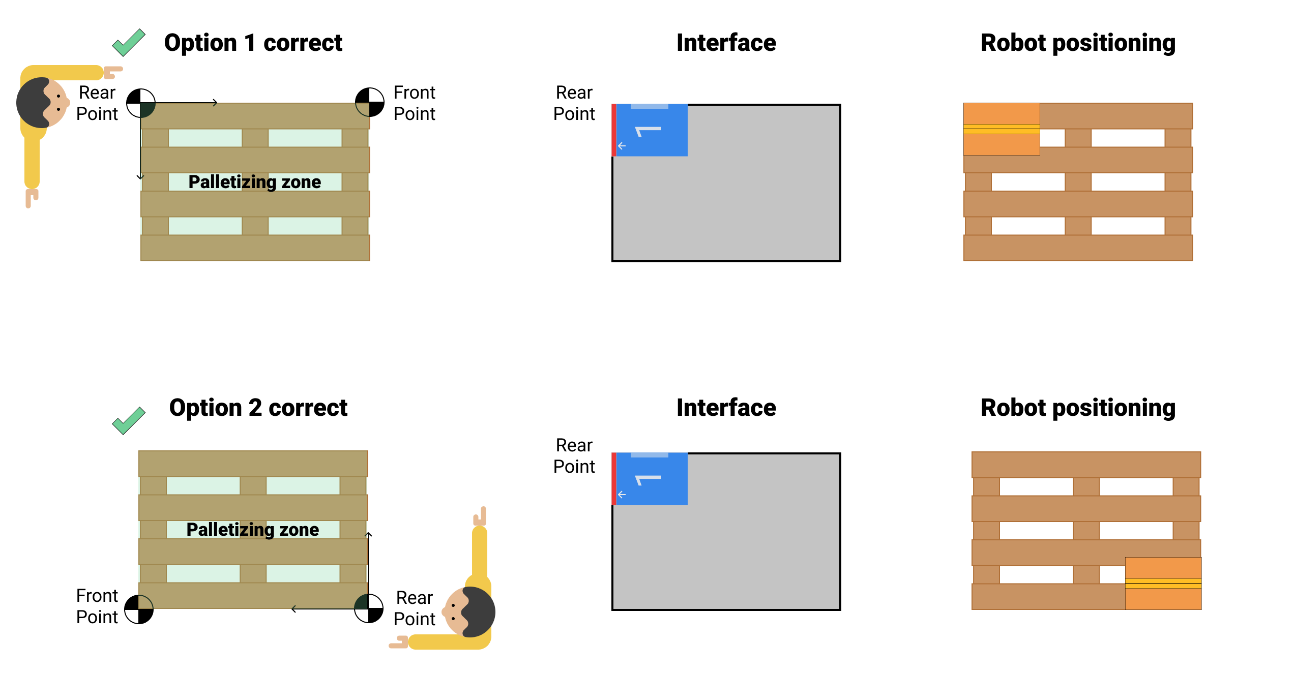
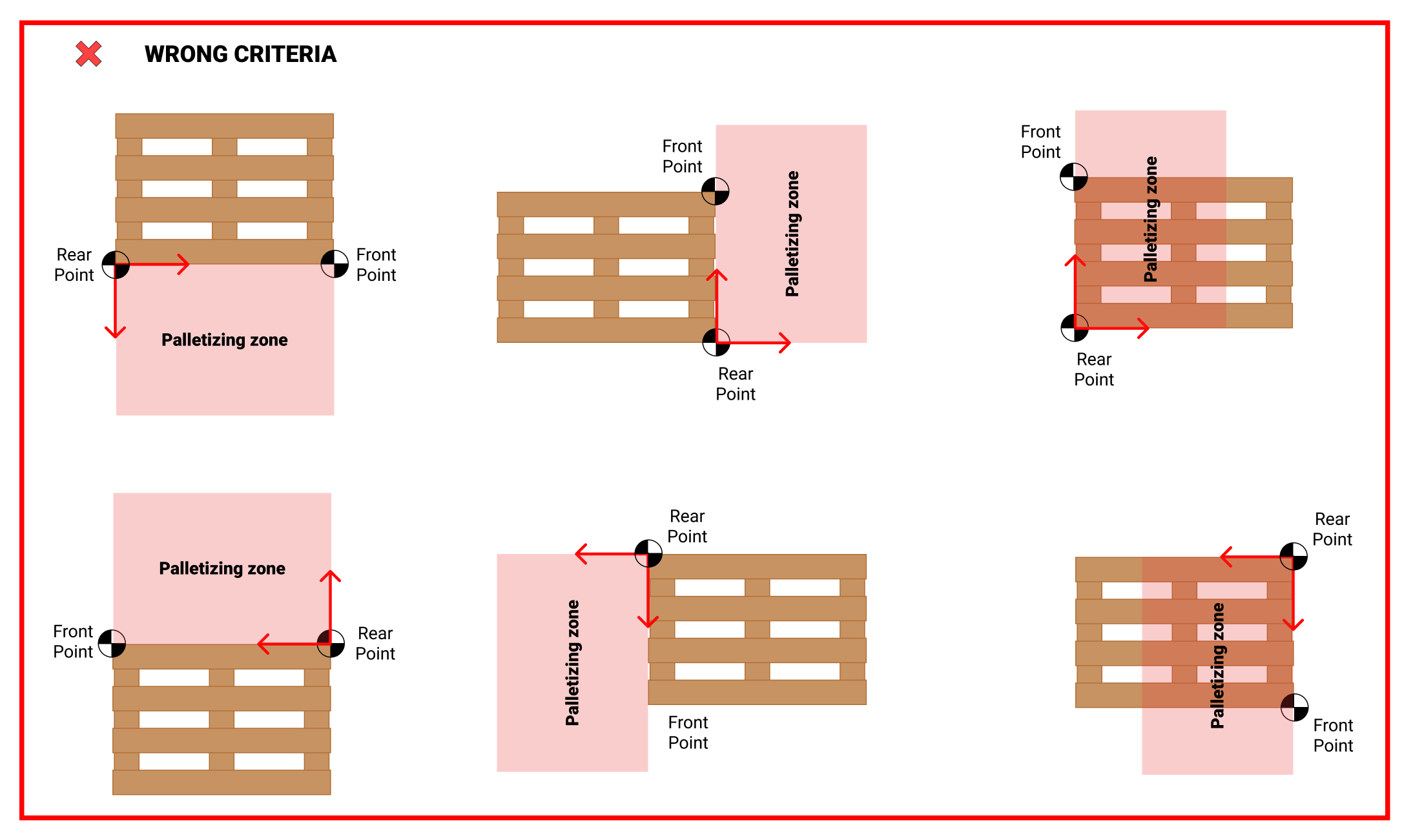
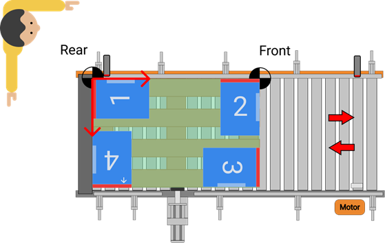
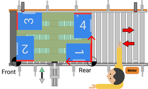
Criteria definition
The vector formed by Front and Rear, must be on one of the long sides of the pallet.
Align the left arm with the long side of the pallet where the Rear and Front points are to be positioned. With the right arm at 90º to the horizontal, the pallet should be at the angle between the two arms.
The Rear point corresponds to the corner closest to the user, and the Front point to the farthest corner.
Choosing the wrong criteria will result in errors when depositing the products in the palletizing station.
#
Obtaining points
Equip the robot flange with a reference system (laser pointer, plumb line, ...).
The reference system shall be aligned with the center of the flange, and the flange shall be parallel to the ground.
Move the robot manually in world coordinates, and without any parameter that alters the reference coordinates.
Once the reference system is over the point to be measured (Rear/ Front), display the coordinates on the robot teach (X and Y), and enter it in the software.
Repeat steps 3 and 4 to take the remaining stitch.
#
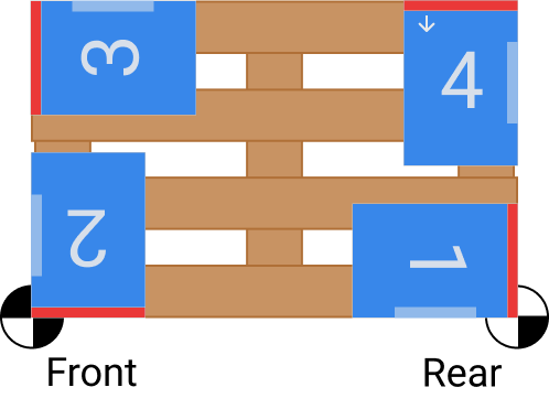
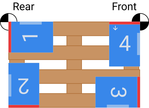
Verification of the configuration
Once all project parameters are configured and the PLC is programmed to interact with the sequence generated with Wepall.
- Create a calibration mosaic, when the gripper dimensions allow it, with 4 boxes at the corners of the pallet and with the product sides (fixed blade and stopper) aligned with the sides of the pallet.
 |
 |
|---|
For more information see the manual Mosaic Edition
- Load the generated source code into the robot, and verify that the robot positions the 4 boxes on the corners of the pallet as the mosaic was designed.
 |
 |
|---|