#
Advanced pickup management
#
Product rotation at pickup
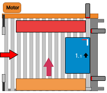
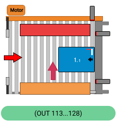
This feature is only physically present with Fork tool and Async tool grippers, as they are the only ones with a fixed part in contact with the product.
For the remaining gripper types, it is considered virtually. Its position can be changed by clicking Finger.
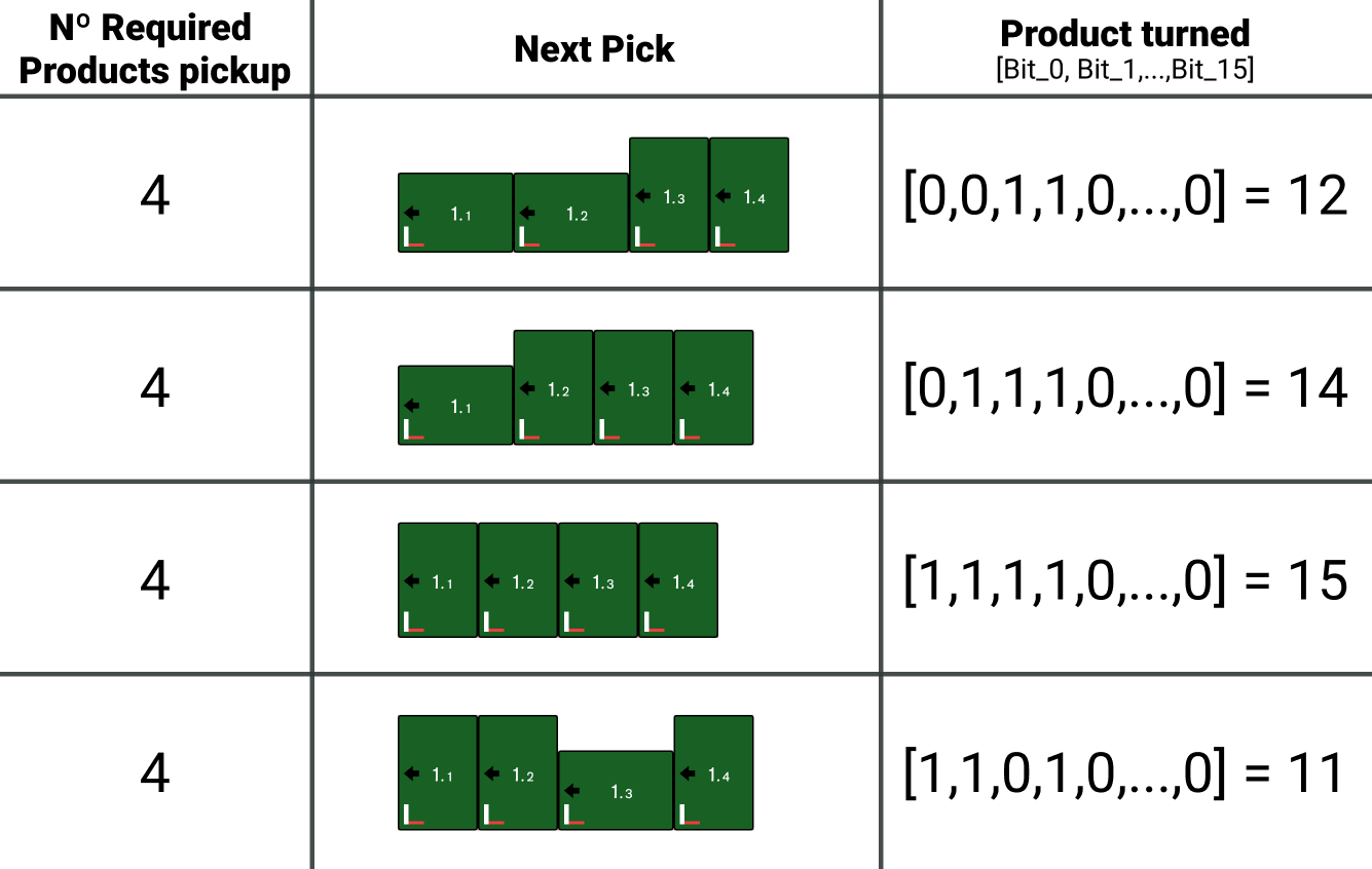
With this function enabled, during the execution cycle the robot will send the PLC, via the communication channel, a group of 16 bits containing the rotation data for each product in that movement.
Each bit corresponds to a product, with bit 0 representing the first product and bit 15 representing product number 16 in the group.
A value of 'False / 0' indicates that the product is not rotated, while a value of 'True / 1' indicates that the product must rotate 90°.
The PLC is responsible for controlling the electromechanical elements at the pickup to rotate the products according to their pickup order.
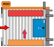
| Normal [Reference Side: Right] |
 |
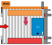
| Product rotated by PLC Integrating a rotation mechanism |
 |
#
Product rotation signals (Robot -> PLC)
Different cases to understand how the interaction between products requested by the robot should work and how the PLC should manage product input.
#
Use of inverted pick coordinates
This feature allows indicating to the robot that inverted pick coordinates should be used for the specified movement.
Under ideal conditions, this corresponds to the gripper being rotated 180° with respect to normal pick coordinates. It can also be used when special pickup positions are required due to product geometry or special pickup designs.
This option is available for all gripper types except Fork grippers.
| Normal [Reference Side: Right] |
 |
| Using inverted coordinates |
 |
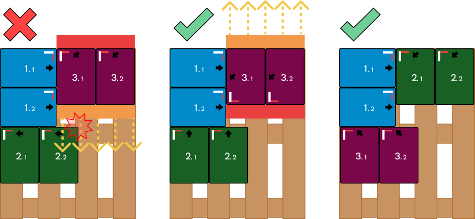
This factor must be considered when designing a pattern, as the behavior of moving parts may cause collisions.
The following example represents the behavior of an Async tool gripper.