
#
Mosaic editing
#
Mosaic editing interface
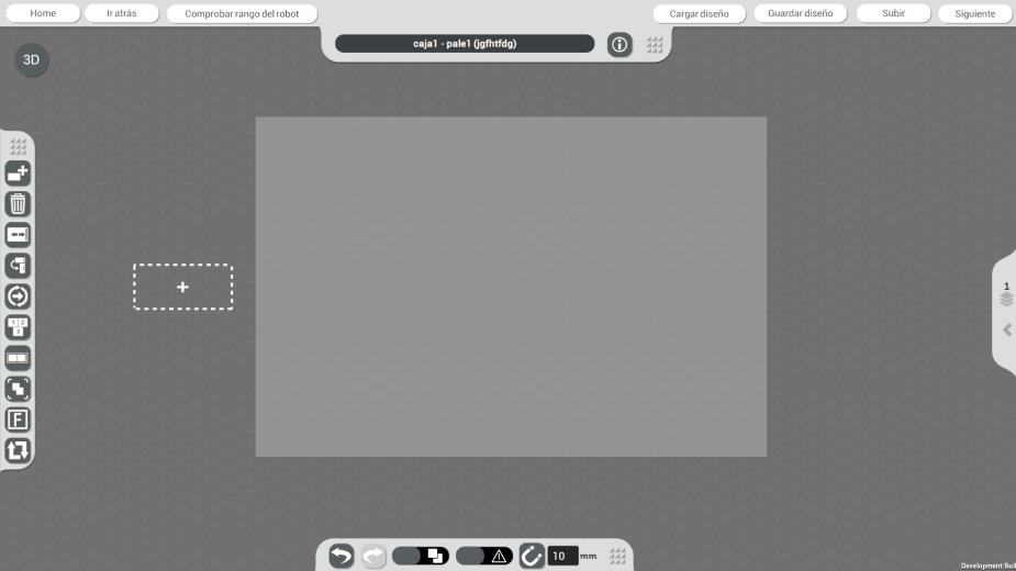
The creation of mosaics with the selected configuration is performed in a simple and versatile interface, as shown in the following image.
#
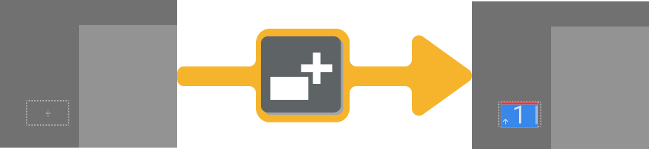
 Add product button
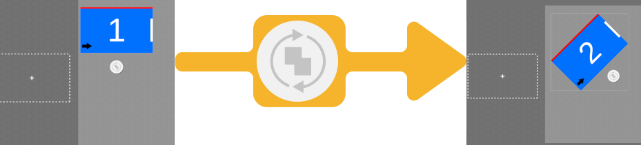
Adds a new product for the user to place on the pallet representation according to the previously defined mosaic. Each click will add one more item, following the numerical order of the layer.
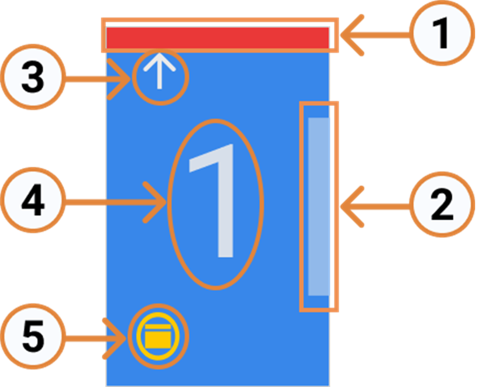
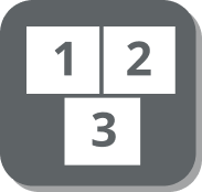
The added products show the following visual references:
| 1. Finger: Represents the fixed blade of the gripper. 2. Stopper: Indicator of the side in contact with the stop limit on the pickup. 3. Direction: Direction of final approach. 4. Number: Displays the order of entry into the pickup. 5. Inverted: Shows that the box uses the inverted pickup coordinates. |
 |
Below you can see how easy it is to add a product in the Wepall🤖 software.
#
Positioning tools
For a detailed adjustment of the products to be palletized in the mosaic, wepall has a series of tools that will allow you to precisely position the elements in the mosaic.
#
 Manually moving an element
Click on the element or group to be moved and without releasing, move it to the desired position.
#
 Rotate element
Select the element to rotate and click on the rotate icon and scroll to the desired tilt. By default it will be done in steps of 45 degrees.
If intermediate positions are required, hold down the Control button on the keyboard, so that the jumps are degree by degree.
#
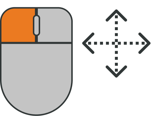
 Move selection (precise movement)
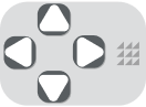
Select the element to be moved and press the arrow keys or the arrow keys on the keyboard to move it in the jumps set in the setting field of the zoom function and with jumps in millimeters.
#
 Delete Button
The function of the Delete button is to delete the selected products. It rearranges the numbering of the remaining items on the screen.
If you want to leave your pallet without a product to place, take a look at the following video. You'll see how easy it is to start from scratch.
#
 Group/Ungroup button
This command allows grouping several products, so that they are accumulated on the pickup, picked up by the gripper at the same time and deposited on the pallet in the same movement.
The groups created can be manipulated and moved as with individual products.
Increase your production 🥇
This function allows you to increase productivity and extend the life of the system by minimizing the number of movements to be performed by the robot. However, it has its counterparts, since, by increasing the number of units picked up, the weight to be moved increases and therefore the inertia of the assembly. It is also essential to check that both the robot is able to move the load up to the required distance, and that the hand can pick up the products safely, preventing them from being thrown during high-speed movements.
As a general recommendation and with a product in optimal conditions (compact, with a uniform load and weight distribution, etc...), the hand should hold at least 2/3 of the product, with a maximum protrusion of 1/3. These indications are indicative, check the technical parameters of the product, the hand and the robot.
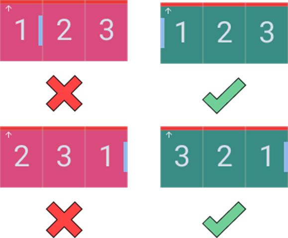
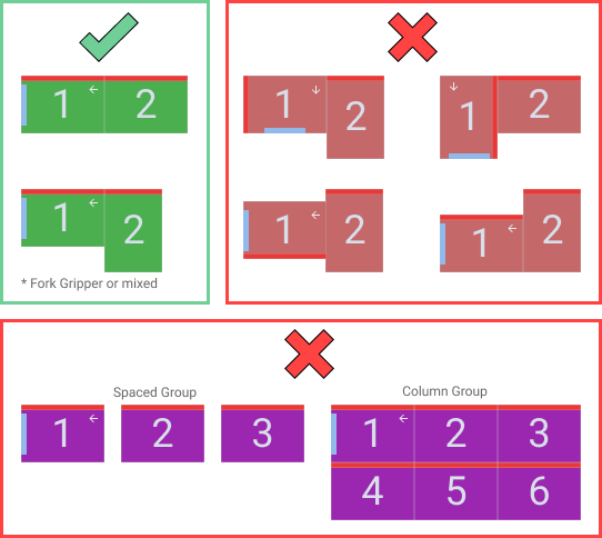
The order of the elements to be grouped must be the order of entry into the pickup of the products to be grouped, with the Stopper mark at the end of the product that first enters the pickup.
#
Examples
Below we are going to see correct and incorrect situations in order to better understand how the grouping option works.
To undo a previously created group, converting them from a multiple take to individual ones.
- Select the group.
- Click on the Ungroup button.
#
 Button sets/Unsets (Rotate/Unrotate) (Finger Button)
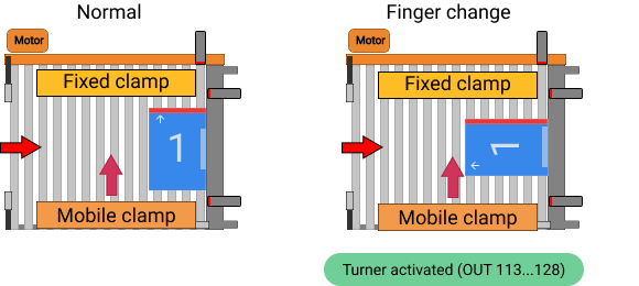
This function changes the fixed contact point of the gripper.
It will only be physically present with the Fork tool and Async tool type grippers, as they are the only ones with a fixed part in contact with the product. In the rest, its presence is considered as virtual. Their position can be changed by pressing Finger.
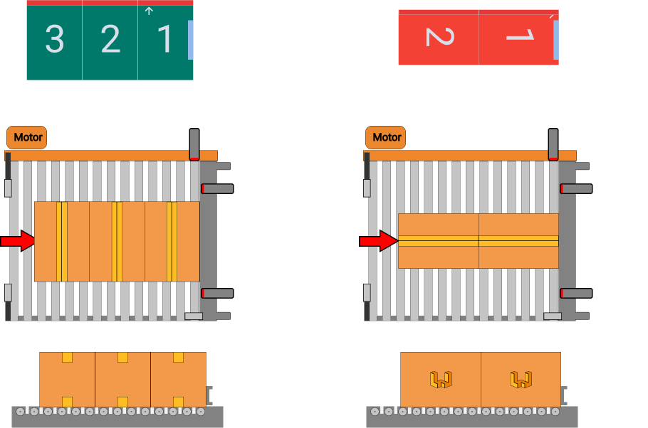
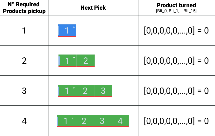
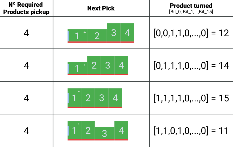
With this function active, during the execution cycle, the robot will send to the PLC through the communication channel, a group of 16 bits with the rotation data of each product of that movement. Each bit will correspond to a product, bit 0 being the first product and bit 15 the 16th product of the group.
A value of 'False / 0' indicates that the product is not rotated, and a value of 'True / 1' indicates that the product should rotate 90º. The PLC will be in charge of controlling the electromechanical elements in the pickup to rotate the products according to their input order.
#
Signals from the Robot to the Plc (Group-Finger)
Different cases to understand how the interaction between the products requested by the robot should be and how the plc should manage the product input.
#
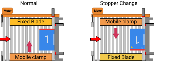
 Stopper Button
This function is used to tell the robot to use the inverted pick coordinates for the indicated movement. Ideally, they will correspond to the gripper rotated 180° with respect to the normal pick coordinates. It can also be used when a special position is needed to pick up the product due to its morphology, as well as for pickup with special designs.
This option will be available for all gripper types, except for the Fork. type.
This factor has to be considered when designing a mosaic, since the behavior of the different moving parts could generate collisions.
The following example represents the behavior of an Async tool type hand.
#
 Direction Button
The approach direction will correspond to the angle at which the robot will approach the product drop-off point.
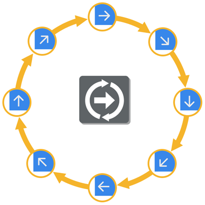
To change the direction, select the element and press the Direction button. The direction will rotate with each press.
This parameter is crucial for a correct palletization, since a wrong choice can lead to a collision with already palletized products.
#
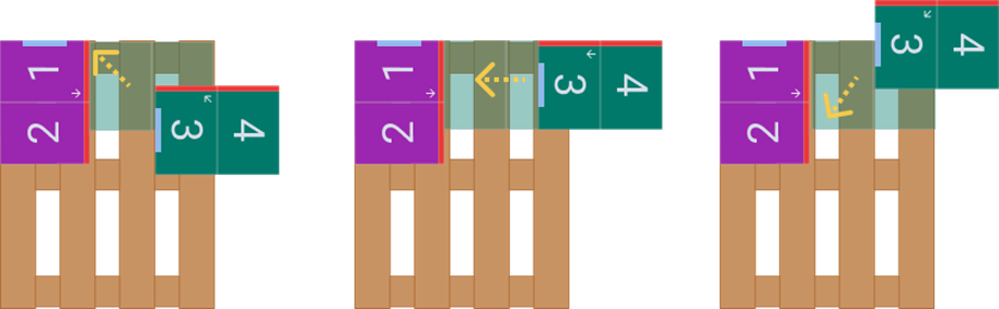
Example 1
The group formed by product 3 and 4 performs a correct approach, with no possibility of collision with the products already palletized.
#
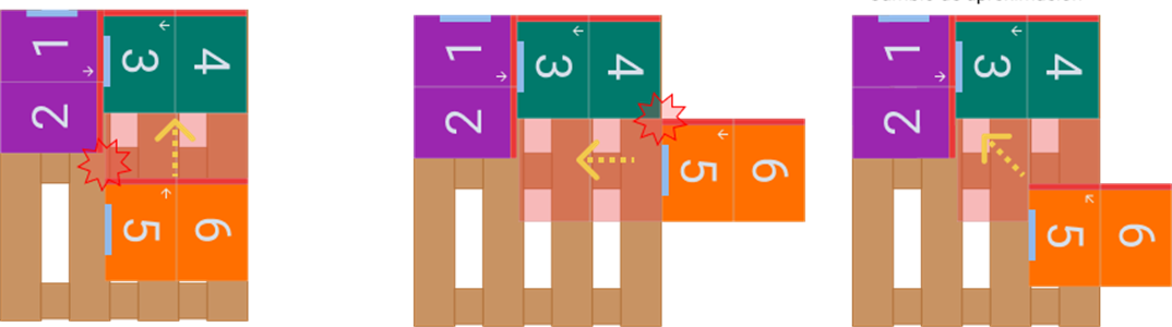
Example 2
The following case shows a situation in which a collision may occur, when making the final approach, one side and the corner of product 5 may come into contact with those of product 2 or 4.
#
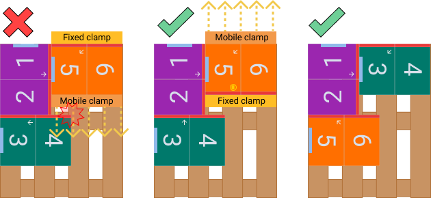
Example 3
As a general recommendation, consider the Stopper mark as a reference point when making the mosaic, since it is a fixed and known point, so that the variation in size that the products may present or the size of the gripper may present collision problems when making the approximation.
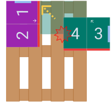
The following image shows a case in which the Stopper orientation is not the right one, so that, if the product or the claw has a larger dimension, product 4 would collide with product 1 and 2.
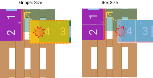
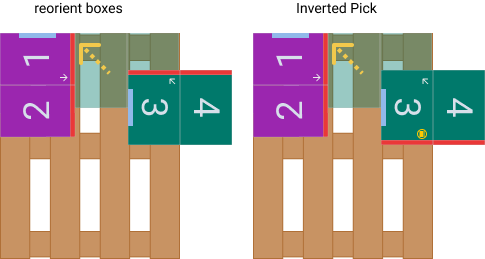
Possible solutions.
#
Example 4
The case depicted shows a situation in which a collision would occur when the wrong approach direction is chosen. Product 7 would collide with product 5 when descending on the pallet.
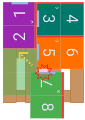
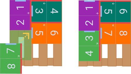
Two possible solutions to this case are shown below.
#
 Reorder button
The Reorder products number button function allows you to numerically rearrange the products that make up a mosaic, without having to manually rearrange the items.
When the Reorder products number button is clicked, the numbering of the tile elements changes to the value 0. mosaic elements changes to the value 0.
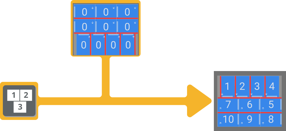
Clicking on the elements will assign a numerical value incrementally. Once the tile has been reorganized, click Finish to apply the changes.
#
 Layer Fill button (Layer AutoFill)
The Layer Fill button fills the number of products that geometrically can contain the indicated pallet, according to the specified product dimensions. It will offer several possible tile options for this purpose.
Warning
Check the mosaic input order and the approach directions.
#
 Center button (Center selected product)
Allows you to center geometrically the elements present with their current distribution in the work area on the pallet surface shown in the interface.
#
 Rotate layer button
This function allows you to rotate the selected layer tile 180° automatically.
Warning
Check the mosaic input order and the approach directions.
#
Steps for the creation of a mosaic
1. Following the previous indications, create the mosaic to be made by the robot. The products inserted in the mosaic can indicate that they are in error by changing color and turning red. The situations likely to generate errors are:
- Overlapping of products.
- Products outside the surface of the pallet.
- The product is not sufficiently supported by the products in the layer below.
When more than 64 products are inserted in a layer, a message is displayed warning that the current pallet and product configuration will result in a very high cycle time value, which is very inefficient and in most cases can affect performance. Do you want to continue anyway?
The mosaic is limited to a maximum of 512 cycles per pallet.
warning
Check the resulting Mosaic, as well as the selected gripper openings, the order of product placement in the mosaic and the approach directions.
#
 Saving existing tile
#
Steps
- To save the existing mosaic for later reuse in another recipe, click on the Save Design icon.
- Select the desired mosaic file and click on Open.
#
 Load existing tile
#
Steps
- To load a previously existing mosaic, click on the Load Design icon.
- Select the desired destination folder and click on Save.
#
 Mosaic design error warning
Products inserted in the mosaic may indicate that they are in error by changing color and turning red. The situations likely to generate error are:
- Overlapping products.
- Products outside the surface of the pallet.
- The product is not sufficiently supported by the products in the layer below.
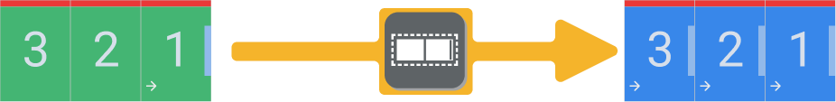
The error notification and design warning can be enabled/disabled as follows.
 Activated Activated |
 Disabled Disabled |
|---|---|
| In the position shown below, the products appear notifying the error. Being in the case described by overlapping. | In the position indicated below, the products will NOT report the error. |
#
 Bottom layer mosaic display
For the design of a stable mosaic, it is necessary to display the products located on the bottom layer, and to ensure that all products have sufficient support on the bottom layer.
In case a product does not have sufficient support on the bottom layer, it will be notified that it is in error by changing its color to red.
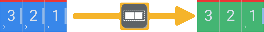
To change the display options, follow the steps below. 🚶👣
 Activated Activated |
 Disabled Disabled |
|---|---|
| At the position shown below, the mosaic of the layer immediately below will be displayed. | At the position shown below, only the tile of the current layer will be displayed. |
#
 Fine-tuning of approximation function
For a precision adjustment of a design in a mosaic, it is required to correctly align all elements. For this purpose, Wepall integrates this function to facilitate the design of mosaics.
This allows that when a product approaches the edges of the pallet or an already positioned product, and the distance is less than the set distance, the product will automatically align with the element.
 Activated Activated |
 Disabled Disabled |
|---|---|
| At the position shown below, the approach function will be activated, and the distance shown will determine the approach range. | At the position shown below, the approximation function will be disabled. The accuracy of the generated mosaics depends on the user. |
#
 Mosaic detailed information
Click on the information icon.
In the drop-down menu, the information related to the current mosaic can be displayed.
To download the mosaic report, click on the PDF download icon. And select the destination folder.
#
 3D preview
Click on the icon , to preview the current layer in 3D. In this mode, if a product is selected, it can be moved, modifying the mosaic.
Click on the layer view icon
 , to preview in 3D the complete mosaic at the current stage of development.
Click on the gravity icon
 , you can check the static behavior of the mosaic generated so far.
#
 Checking robot range
This function allows to check if the robot is able to reach all the positions of the mosaic sequence with the set co-setting.
Mathematical algorithm 👨💻
Said algorithm will be performed on the wepall servers. 💻 ☁️ 🖥️ ☁️
warning
If the project nodes are not properly configured, the results of the study will not be valid.
In order to check the ranges press:
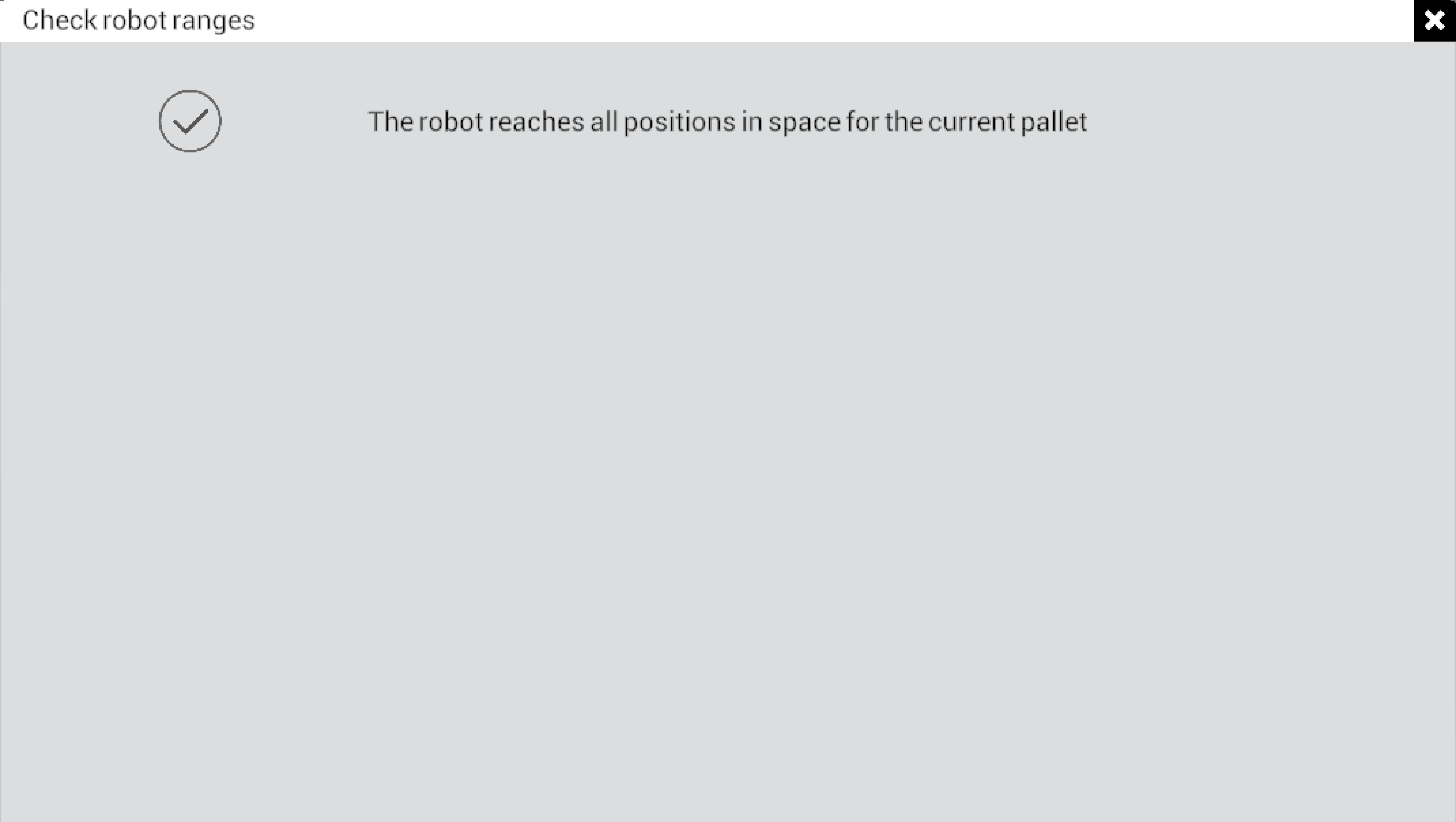
- In the mosaic design screen, click on the Check range of the robot button.
- If the robot is able to reach all the positions of the mosaic, it is shown in the attached dialog box confirming it.
#
Error evaluation
If an error is detected in any of the points of the path, an informative table is displayed with the following data.
- Layer. Layer where the problem has been detected.
- Cycle. Within the movements of that layer, and taking into account the order of placement, in which of them the problem has been detected.
- Pose. Point of the path of Wepall in conflict.
When the dialog box closes, you automatically see the 3D view, which shows the conflicting elements by flashing red.
In case of not configuring some of the "critical" parameters (Pick or Rear/Front coordinates...) in the project, a red mosaic is displayed, the whole mosaic is wrong.